Feeder, carrier and modeled fault branch / ACR1 / stills

Continuous payload custody.

A complete still alternative to video. The original full-resolution scientific figures and CAD view provenance remain available in the asset register.

Return to film · Read complete transcript
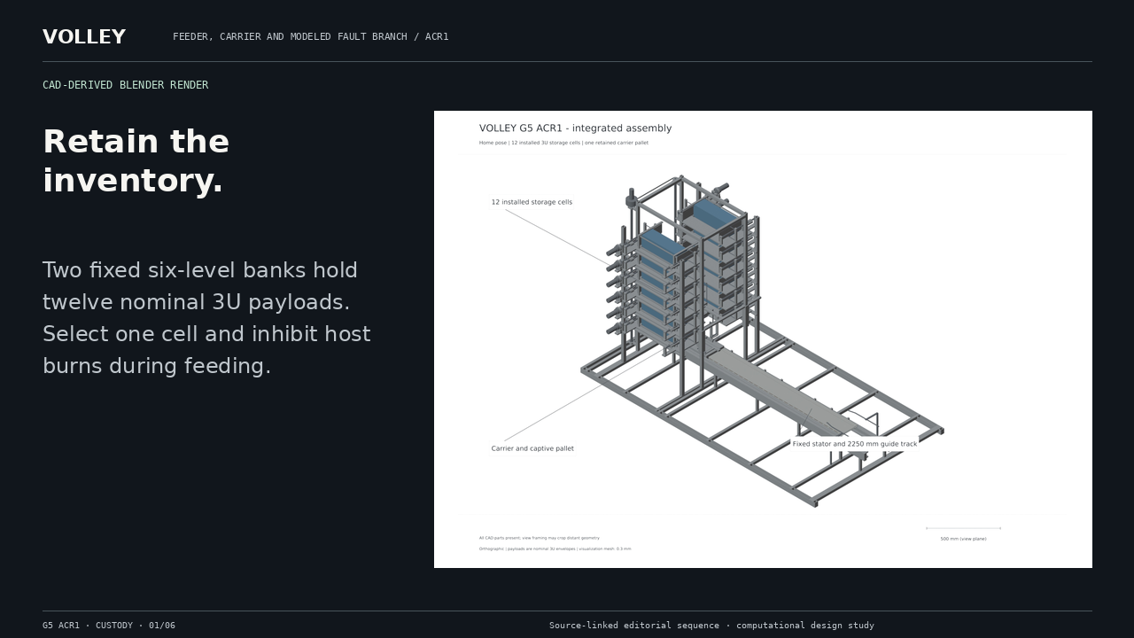
Retain the inventory. Two fixed six-level banks hold twelve nominal 3U payloads. Select one cell and inhibit host burns during feeding.
0–10 s · Retain the inventory.

Two fixed six-level banks hold twelve nominal 3U payloads. Select one cell and inhibit host burns during feeding.

CAD-derived Blender render
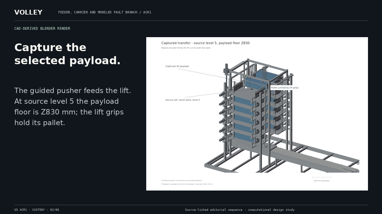
Capture the selected payload. The guided pusher feeds the lift. At source level 5 the payload floor is Z830 mm; the lift grips hold its pallet.
10–20 s · Capture the selected payload.

The guided pusher feeds the lift. At source level 5 the payload floor is Z830 mm; the lift grips hold its pallet.

CAD-derived Blender render
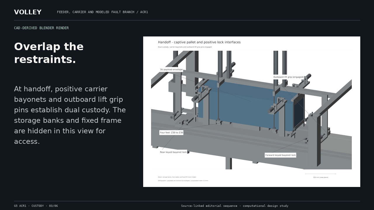
Overlap the restraints. At handoff, positive carrier bayonets and outboard lift grip pins establish dual custody. The storage banks and fixed frame are hidden in this view for access.
20–32 s · Overlap the restraints.

At handoff, positive carrier bayonets and outboard lift grip pins establish dual custody. The storage banks and fixed frame are hidden in this view for access.

CAD-derived Blender render
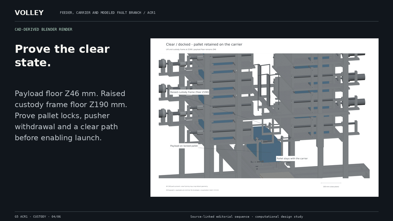
Prove the clear state. Payload floor Z46 mm. Raised custody frame floor Z190 mm. Prove pallet locks, pusher withdrawal and a clear path before enabling launch.
32–44 s · Prove the clear state.

Payload floor Z46 mm. Raised custody frame floor Z190 mm. Prove pallet locks, pusher withdrawal and a clear path before enabling launch.

CAD-derived Blender render
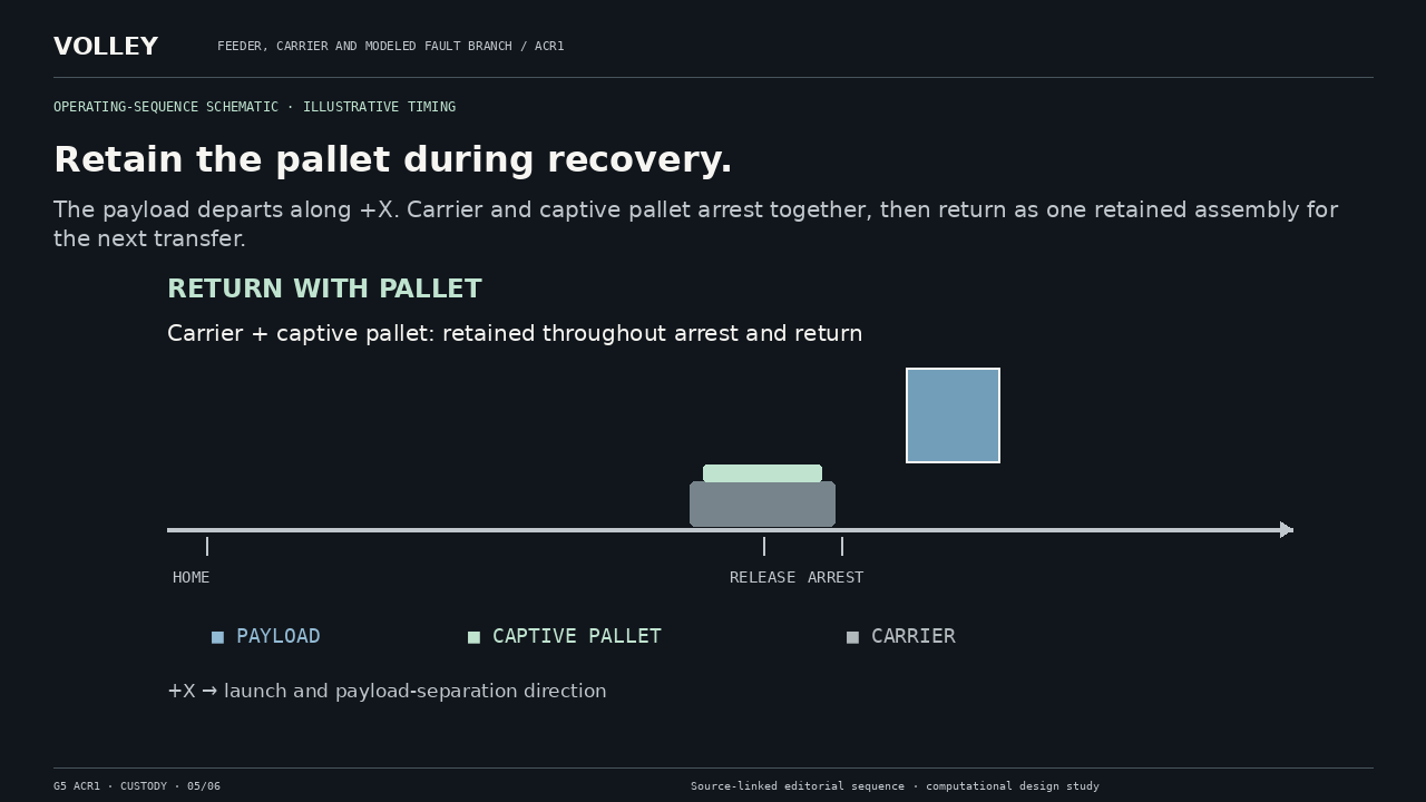
Retain the pallet during recovery. The payload departs along +X. Carrier and captive pallet arrest together, then return as one retained assembly for the next transfer.
44–60 s · Retain the pallet during recovery.

The payload departs along +X. Carrier and captive pallet arrest together, then return as one retained assembly for the next transfer.

Operating-sequence schematic · illustrative timing
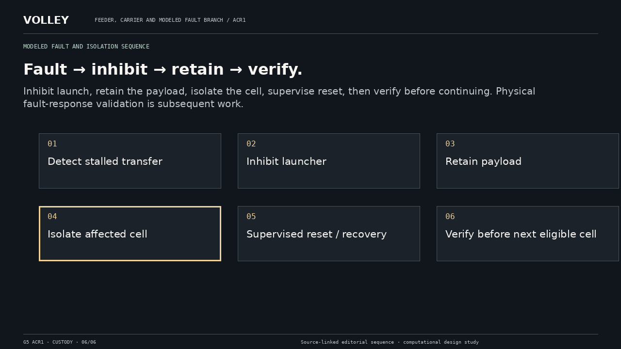
Fault → inhibit → retain → verify. Inhibit launch, retain the payload, isolate the cell, supervise reset, then verify before continuing. Physical fault-response validation is subsequent work.
60–78 s · Fault → inhibit → retain → verify.

Inhibit launch, retain the payload, isolate the cell, supervise reset, then verify before continuing. Physical fault-response validation is subsequent work.

Modeled fault and isolation sequence