Guided lead-screw feeder
FM08-R3 selected academic design
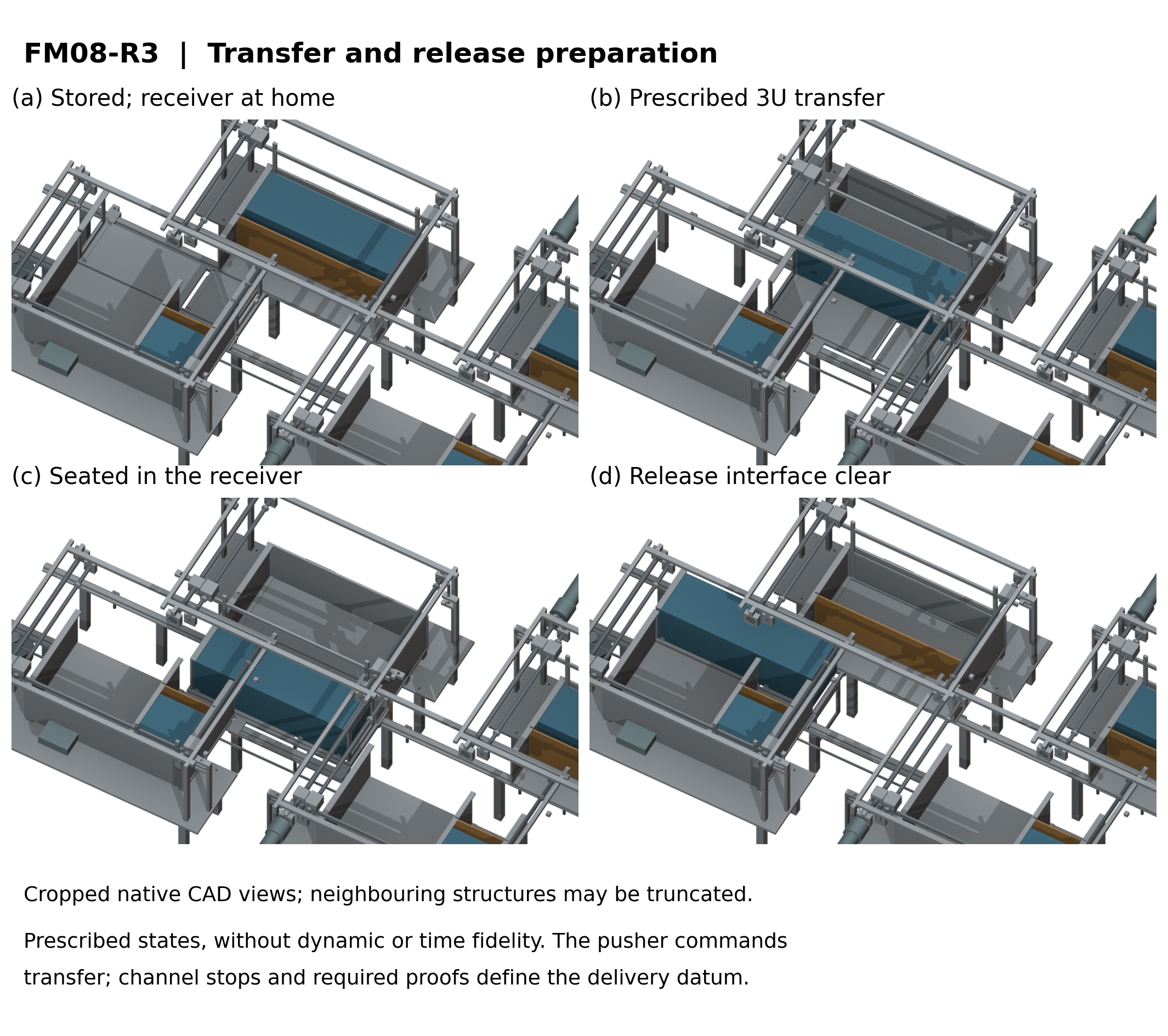
The selected architecture uses separate restrained cells, a guided lead-screw pusher and one indexed receiver. Dedicated 1U spacers stay in the cassette; a capped channel and closed far-side stops contain the spacecraft; receiver capture is proved before the pusher returns. FDR10 compares the top three concepts using common inputs and records the seven-architecture ranking.
| Architecture | Weighted judgment /10 | Decision |
|---|---|---|
| Guided lead screw | 7.30 | Selected academic architecture |
| Rack and pawl | 7.10 | Retained runner-up |
| Spring and two gates | 6.90 | Alternative; spring force and controlled reset require redesign |
Weights: safety 35%, packaging/mass 25%, positioning 20%, cycle/power 10%, manufacture 10%. The ranking is sensitive to priorities; it does not estimate reliability. Selected-design evidence includes native CAD/STEP, nominal motion, declared analytical sizing/load/tolerance screens and executable four/twelve-cell interlock cases. Physical qualification and precision measurements remain future work.
Complete selected-design package · Alternative concept archive
Historical geometry and numerical studies
Evidence through 22 October 2026: FM06-R1 component/contact studies, FM07-R6 nominal rotary clearance and the separate common-boundary feeder comparison. Seven Gen6 concepts share a 200 mm lateral transfer task for passive 1U/3U envelope surrogates. The receiver, gate, captive transfer and arrest requirements are evaluated separately from the launcher motor.
No feeder is selected or released for manufacture. Native CAD and a clear pose do not demonstrate handoff, safe power-off restraint, joint strength, complete installed hardware or reliability. Gen5 remains the evaluated configuration with its original failures.
Complete-angle clearance and contact-model diagnosis
RVC01 evaluates the separate FM07-R6 candidate. A 0.25 mm gate-panel relief retains the hinge, locks and upper edge. Four complete rotary intervals pass the nominal native-distance screen; the smallest guarded conservative bound is 0.0098846 mm. Eight assembly and two gate STEP files have checked exchange records. This does not establish manufactured or loaded clearance.
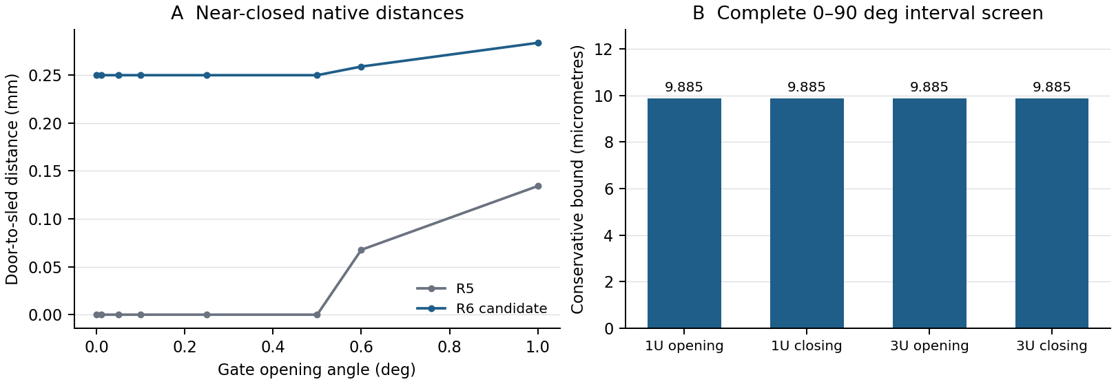
Native CAD, STEP, interval method and report.
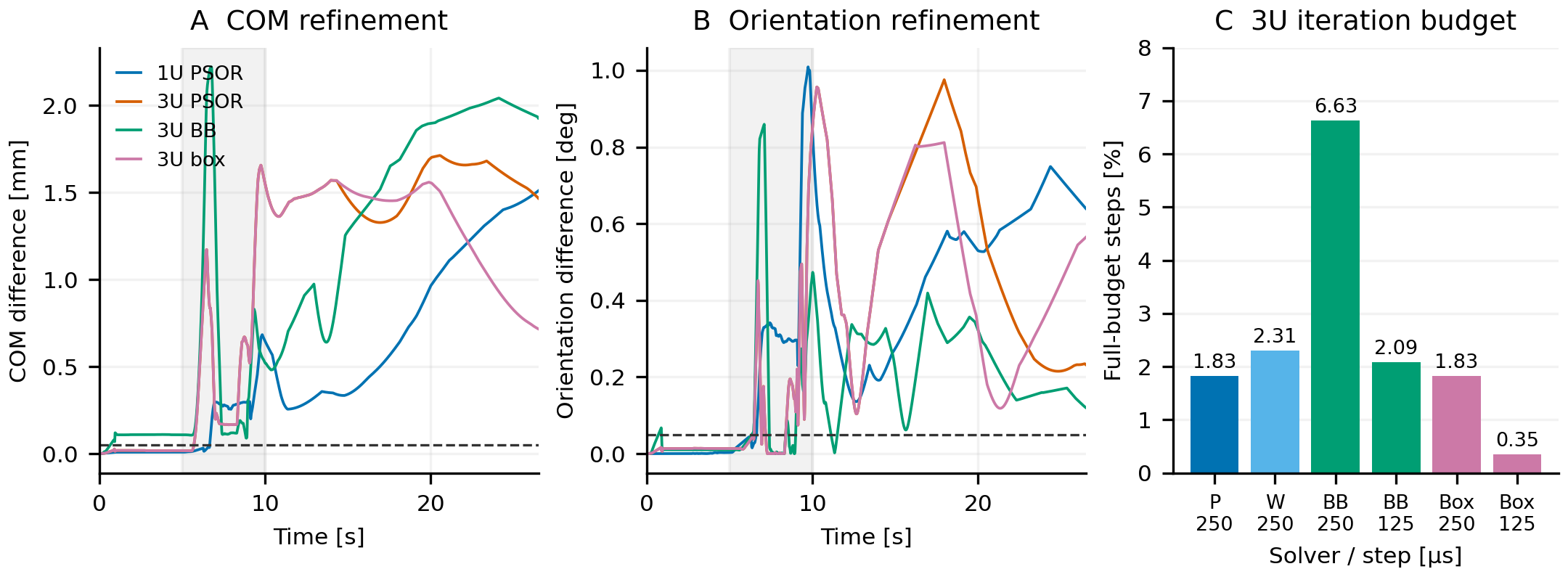
FCE13 adds six completed native Chrono diagnostic runs on FM06-R1. Instrumentation reproduces the original baseline byte for byte. Original PSOR, native BB and an exactly equivalent box-core representation do not satisfy the unchanged pose-refinement criteria. No correction is qualified; these contact results do not validate FM07-R6.
Seven concepts on a common four-payload boundary
FDR09 models two 1U and two 3U payloads with one common receiver. Seven R1 native/STEP assemblies have separate exchange readback. A restricted lead-screw R2 trim clears the checked nominal payload corridor and identified housing overlap. Full carriage, loaded support, tolerance, fault and insert-custody gates remain open; no feeder was selected in that study.
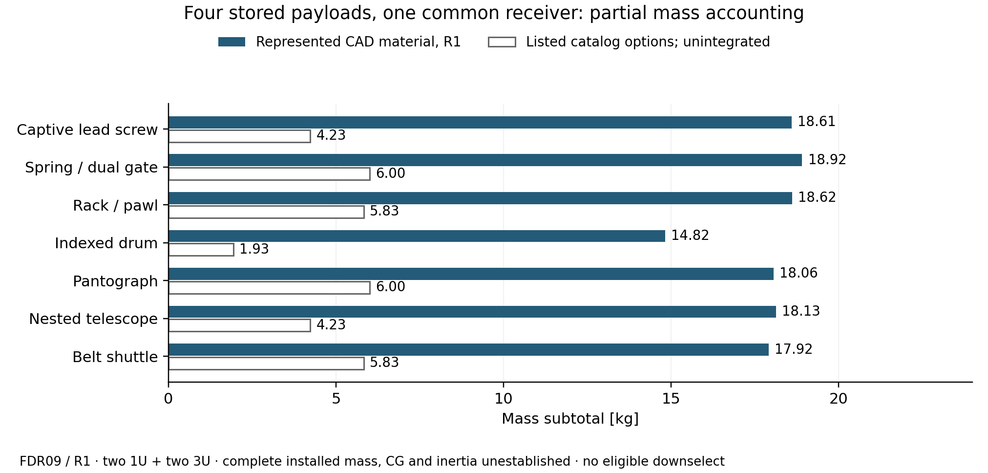
Ten native/STEP pairs, BOM, component sources, exact geometry findings and checks.
Release and empty-carrier reset geometry
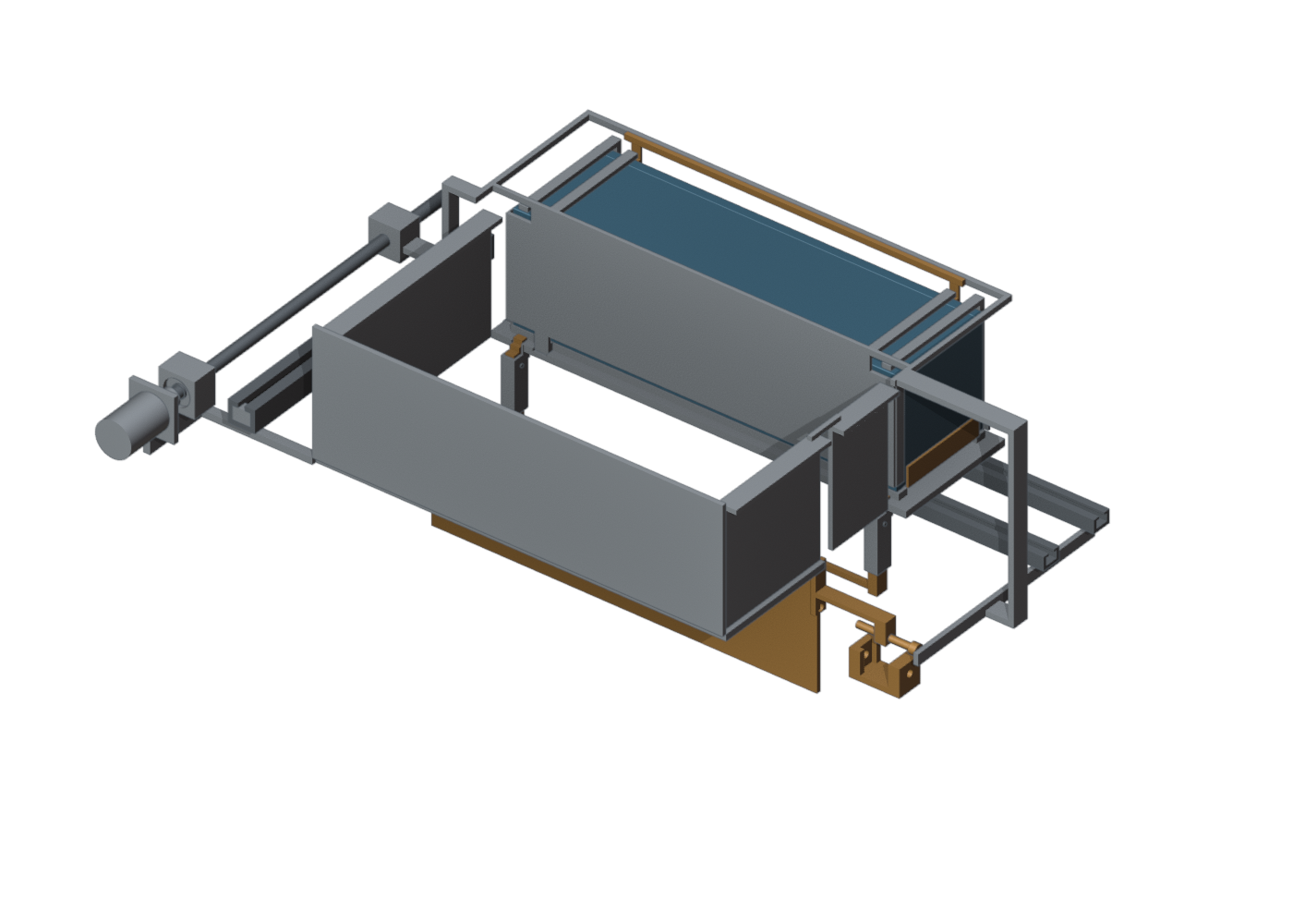
FM07-R5 adds captive receiver-lock pins, a hinged forward exit gate and prescribed empty-carrier reset. The 1U and 3U nominal cycles have 46 checked states, 34 additional door-angle samples and 40 continuous linear sweeps. Twenty native/STEP assemblies and 74 part exchanges pass independent readback. Rotary motion remains discretely sampled; these checks do not establish loaded clearance or hardware reliability.
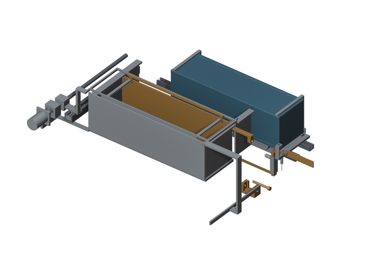
Self-contained geometry, STEP parts, native application capture and report. All seven concepts remain subject to the controlled selection gates.
21 October: geometry, stiffness and native contact review
The separate FM06-R1 research revision contains 30 native assembly/STEP poses, 70 independently checked reference part exchanges and 28 continuous prescribed rigid-translation checks. A backstop junction missed by solid-validity checks is corrected. These are nominal geometry results, not manufacturing or loaded-clearance acceptance.
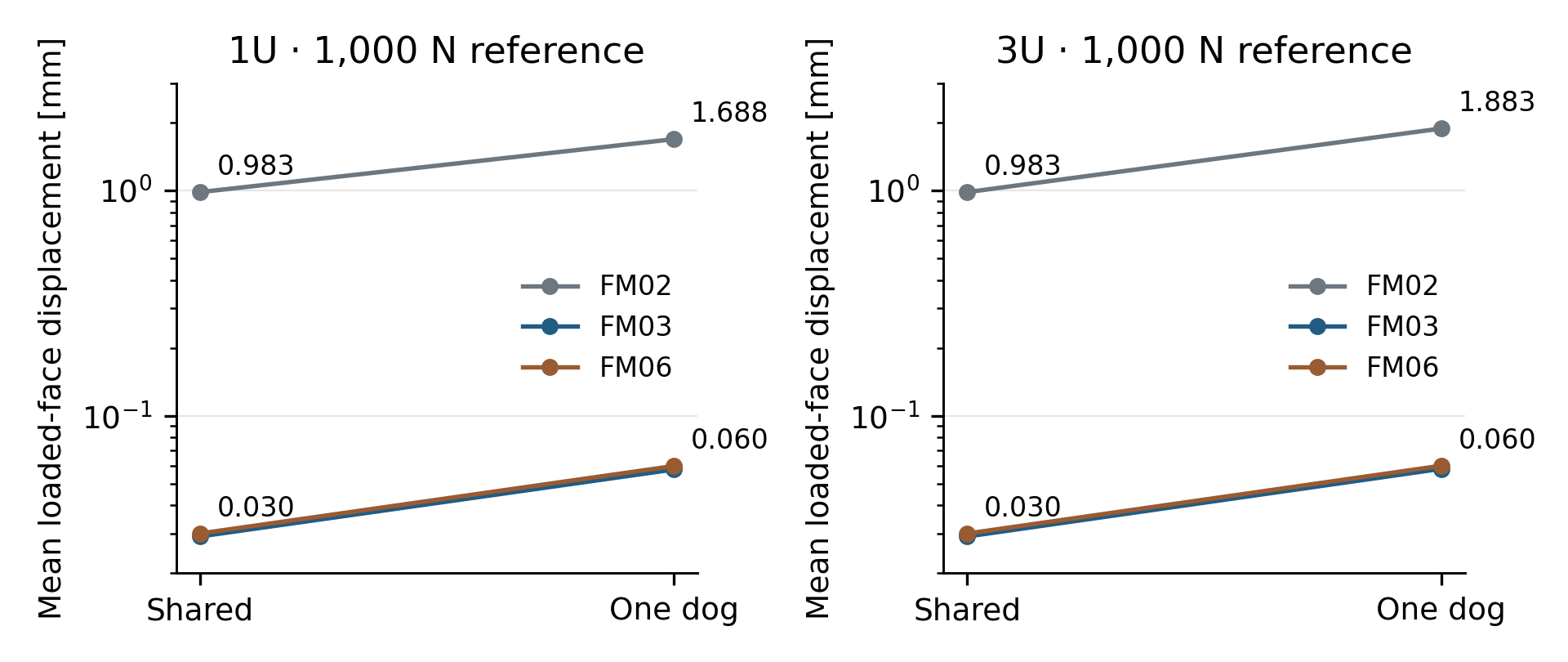
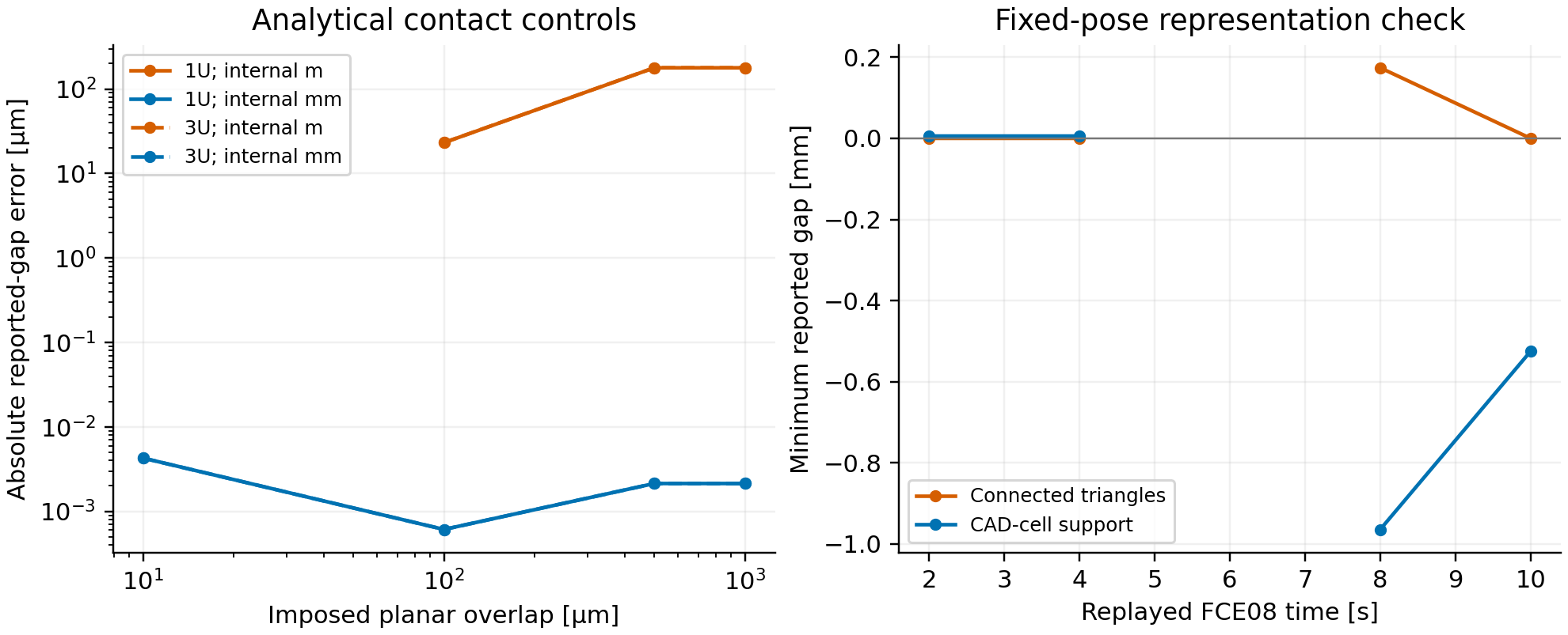
The twelve-case capture includes ten endpoint sequences and two injected-fault aborts. Eighty-four selected full-solid poses bound the recorded geometric residuals; they do not certify continuous loaded clearance. Current contact-method report, source, controls and native outputs.
Self-contained report, native inputs, CAD/STEP, checks and retained failures. All seven were unselected at this historical study revision. Evaluated Gen5 is unchanged.
Earlier candidate geometry · 19 October
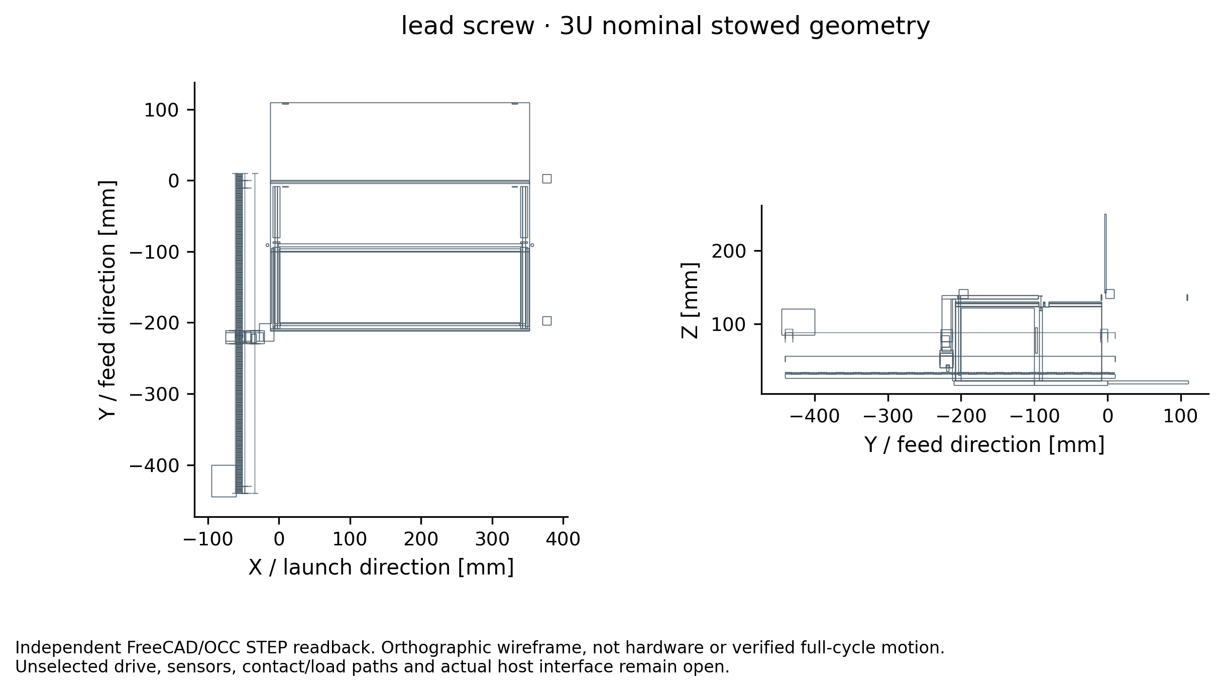
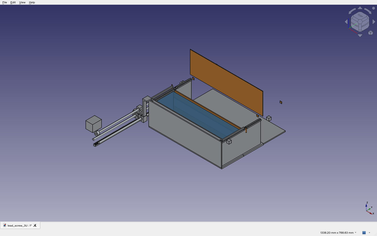
The earlier FDR-08 package contains fourteen editable native assemblies and twenty-eight STEP states. Exact intersections are checked at nine transfer stations, one stowed pose and five gate heights per case. The rectangular payload sweep covers only straight translation against fixed feed-state geometry. Nonlinear indexing, handoff, return, loaded deformation and contact are outside that proof.
What the mechanisms demand
| Candidate | Useful feature | Decisive unresolved concern |
|---|---|---|
| Lead screw | Reversible positive displacement | Nut, bearing, brake and vacuum-duty ratings; no reliance on friction self-lock |
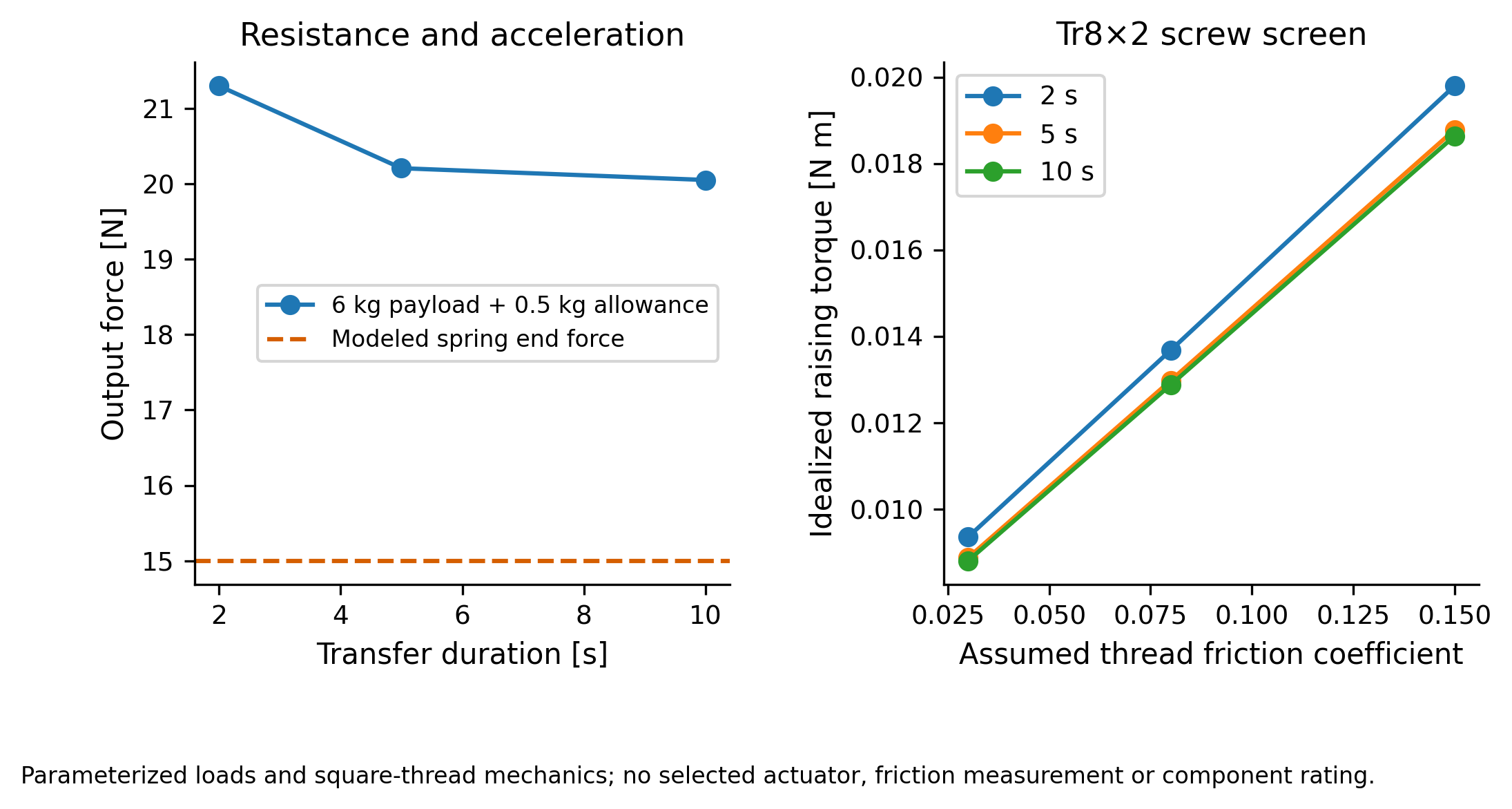
| Spring / two gates | Stored feed energy | 15 N end force fails higher resistance cases; governor and dual-barrier proof |
| Rack / pawl | Discrete indexing | Tooth engagement, bounce, holdback and partial strokes |
| Indexed drum | One shared transfer window | Loaded rotor indexing, envelope, independent cell locks and common-path blockage |
| Pantograph | Compact folded linkage | Near-flat force, joint play and independently sequenced platforms |
| Telescoping carriage | Compact retracted length | Stage order, overlap, positive stops and anti-separation |
| Belt shuttle | Low moving drive mass | Tension, creep, breakage and independent arrest |
Retain adverse cases
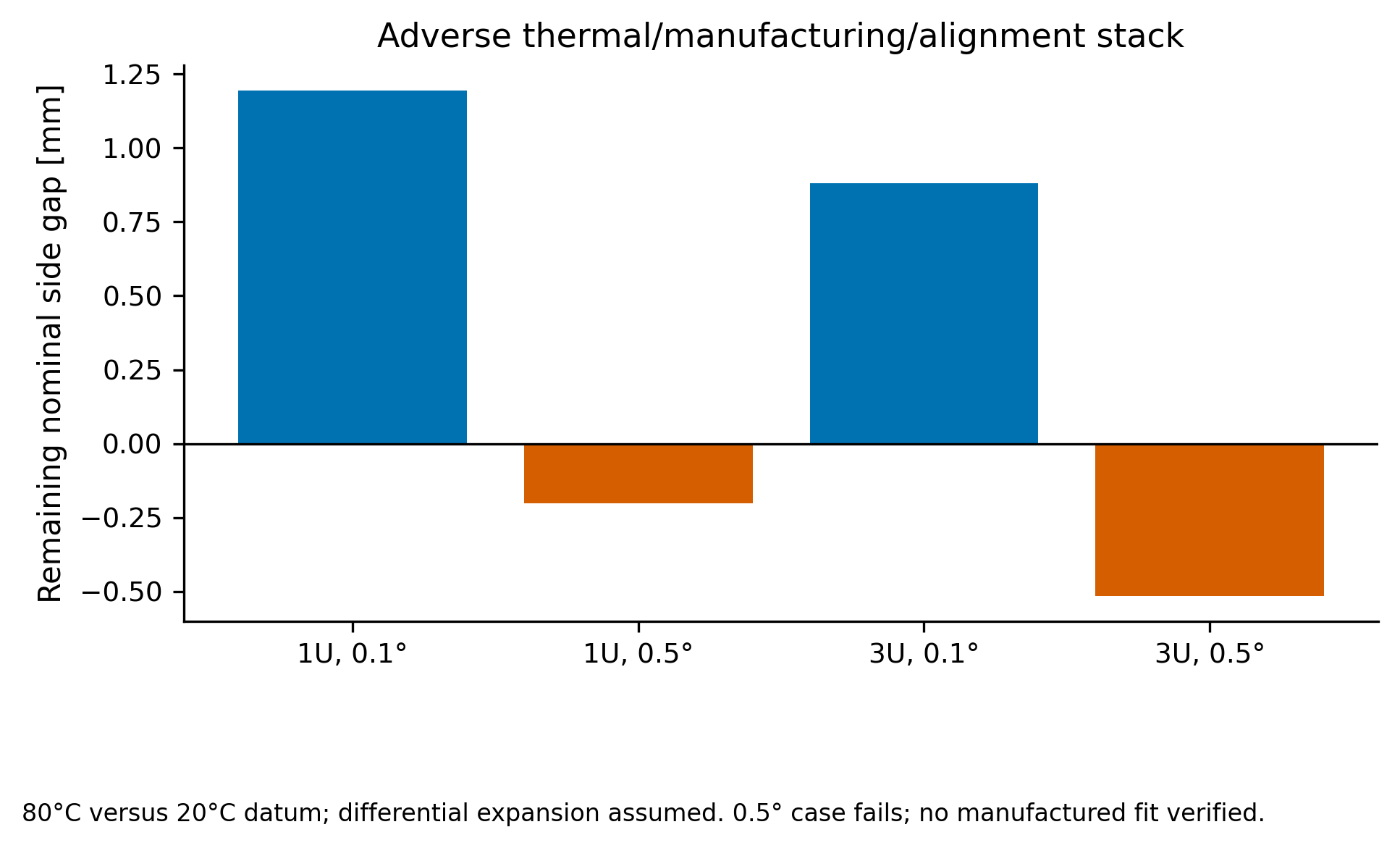
The capture-rack cantilever screen also fails adverse mean-arrest cases: its 1 mm tooth root reaches approximately 1,973 MPa nominal bending under the largest computed mean force. Actual peak force and a selected material allowable are unknown; this is a redesign finding, not a working positive lock.
Native structural output, within its fixture
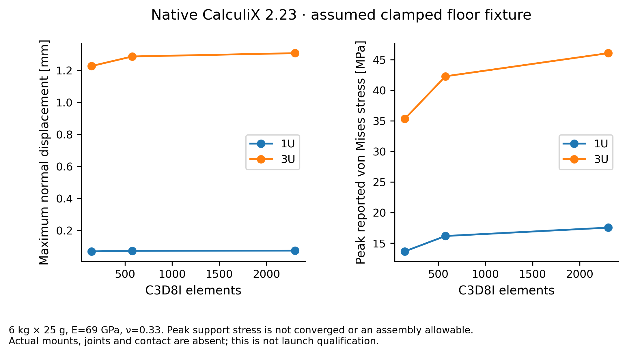
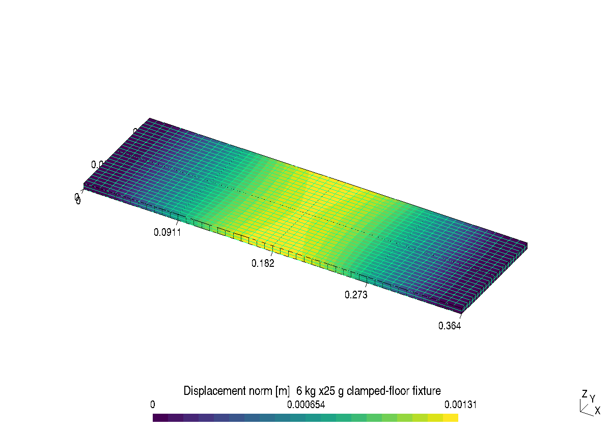
Read the engineering record
Report, local source/CAD archive, material BOM/CG/inertia, issue dispositions and native results. All seven research candidates in Labs. Safety-led ordinal scores remain hypotheses with overlapping intervals; incomplete mandatory evidence prevents a final selection.
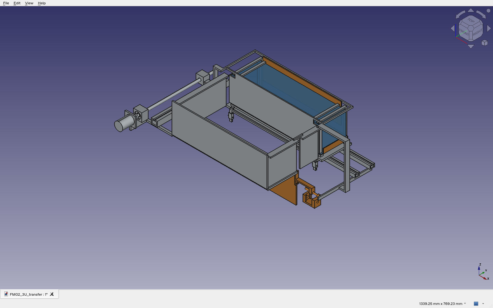
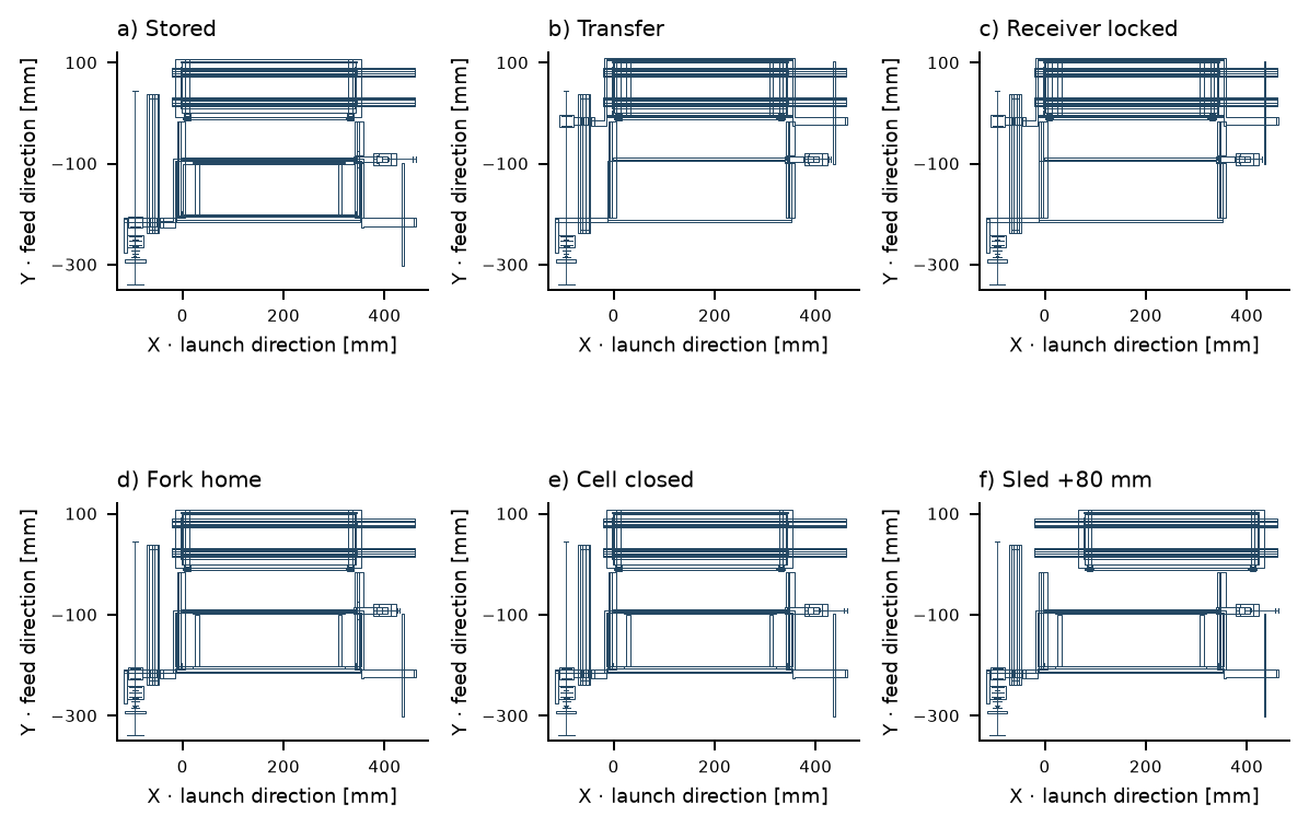
FM-02: revised captive handoff and actuation screens
20 October 2026. A 12 mm underfloor receiving frame and two endpoint crosspins replace the tall latch. The restraints now belong to a connected sled. Twenty-eight native/STEP poses and 26 continuous prescribed rigid-translation phases have no represented penetration. This is captive handling; launch, free separation and complete reset are not simulated.
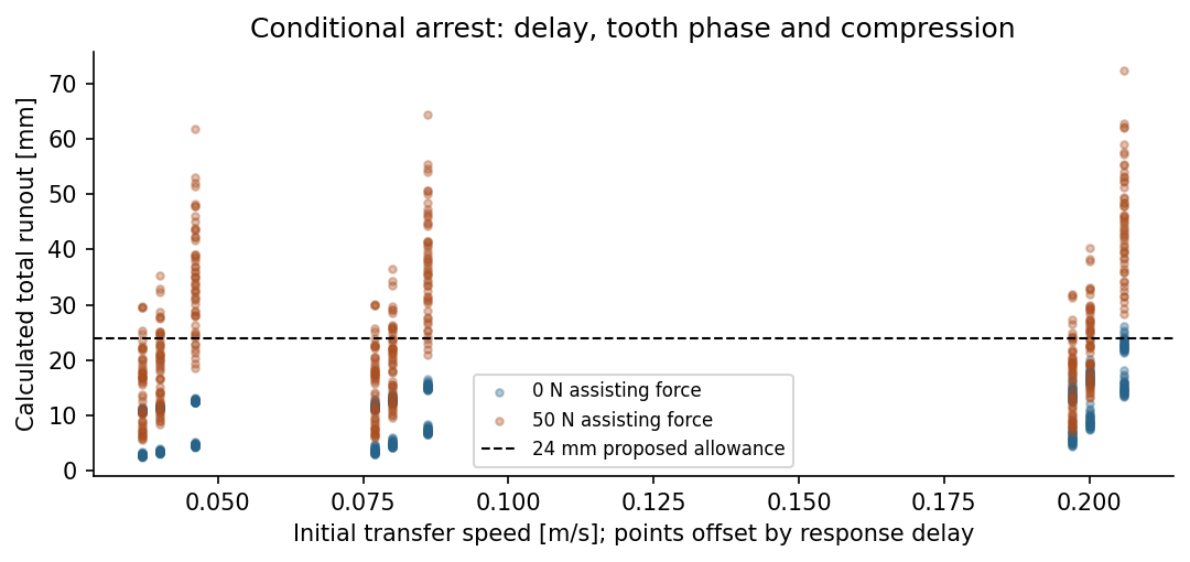
All 972 sampled ground-drive decisions agree with polynomial extrema/integrals. The study retains 115/324 nonpositive fit residuals, 12/54 winding-temperature failures, 96 brake no-stop cases and 72 finite runouts above the proposed allowance. The integrated drive and braking candidate are not installed in this CAD.
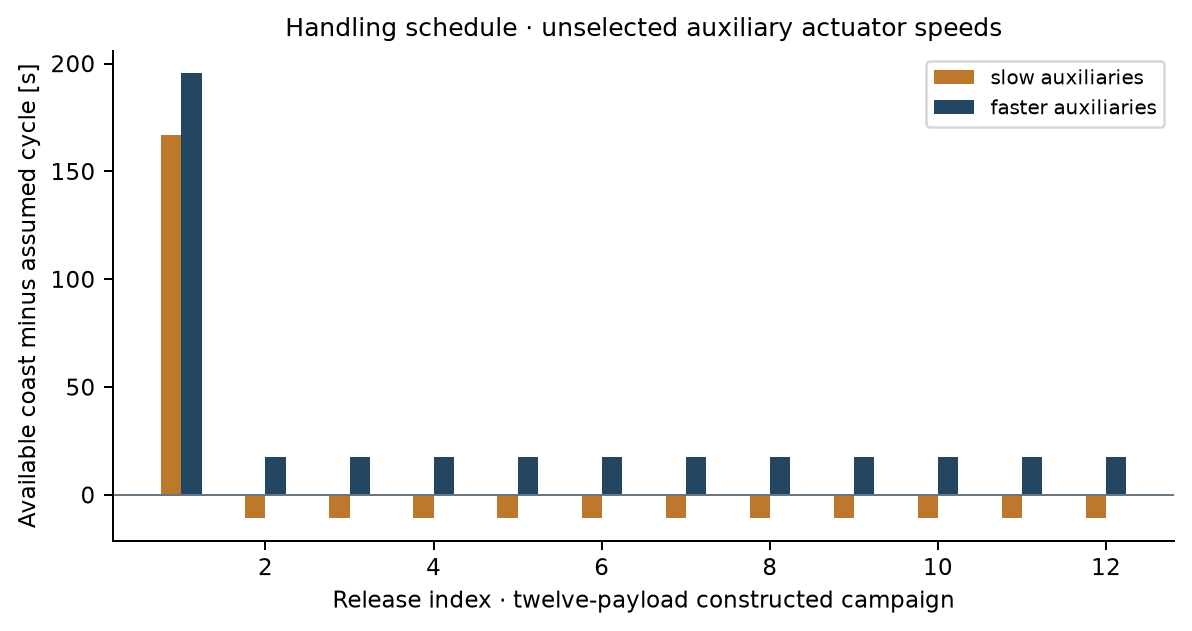
Self-contained nine-page report, source, native CAD/STEP, reference sheets, logs, failed cases and provenance. Axial pin retention, actual actuation, loaded contacts, complete deployment/reset and installed four/twelve-cell integration remain open. All seven were unselected at this historical study revision.
CT-01: continuous prescribed-cycle follow-up
19 October 2026. A separate captive-transfer coupon checks receiver capture and fork withdrawal across a complete prescribed rectilinear sequence. The gate retracts down through a floor slot; this requires 120 mm gate travel and new under-deck accommodation. Receiver locks occupy separate motion bands.
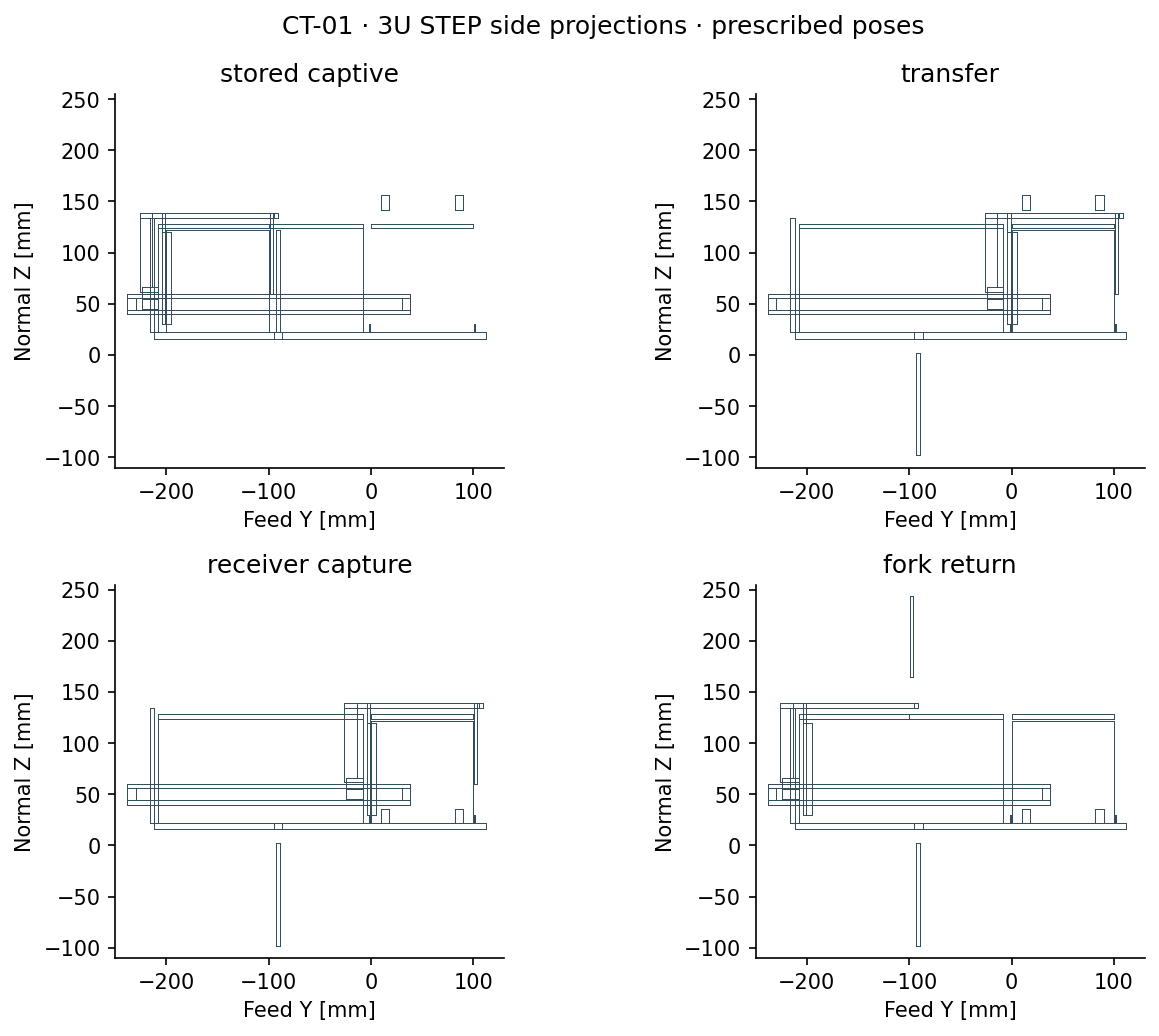
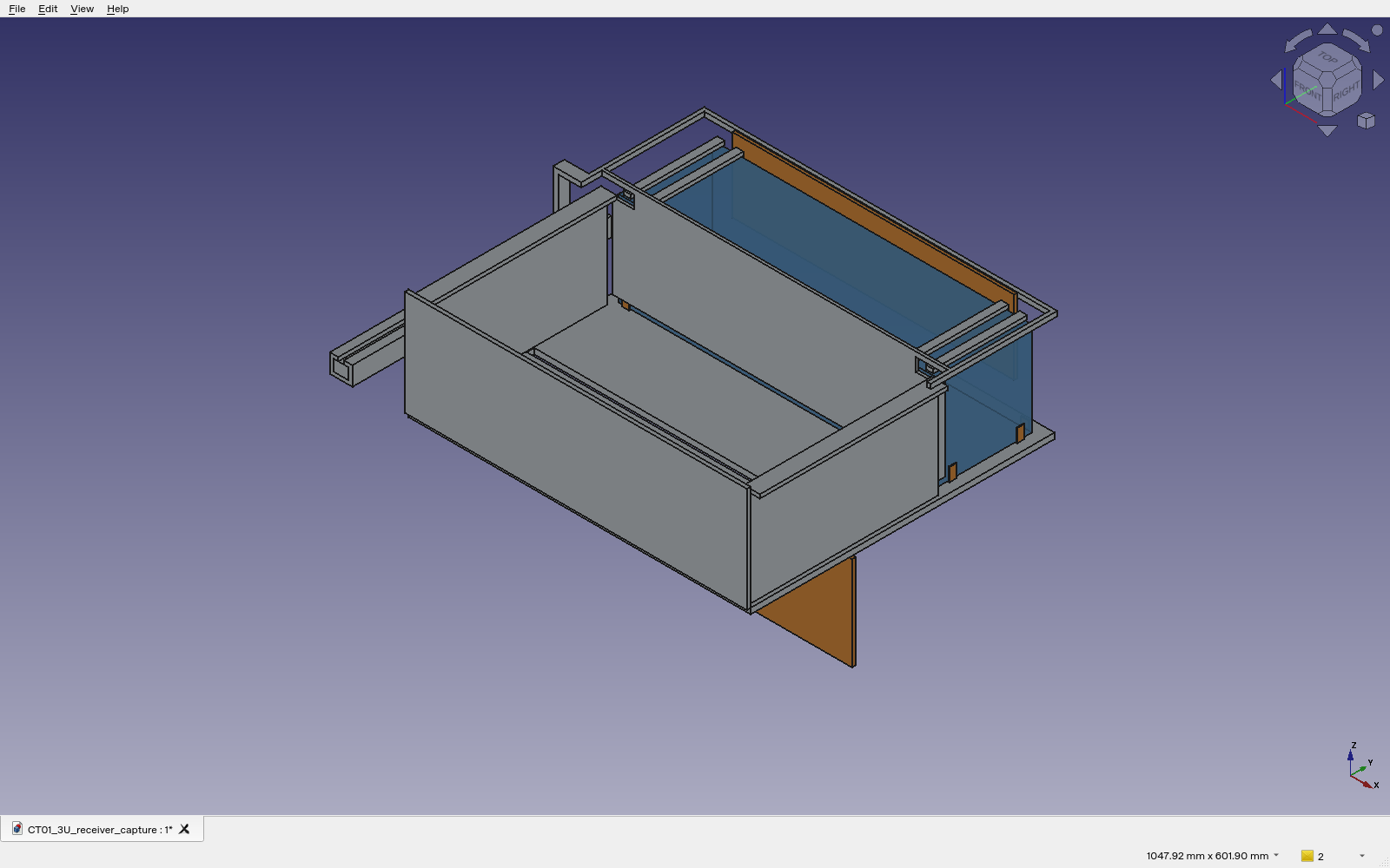
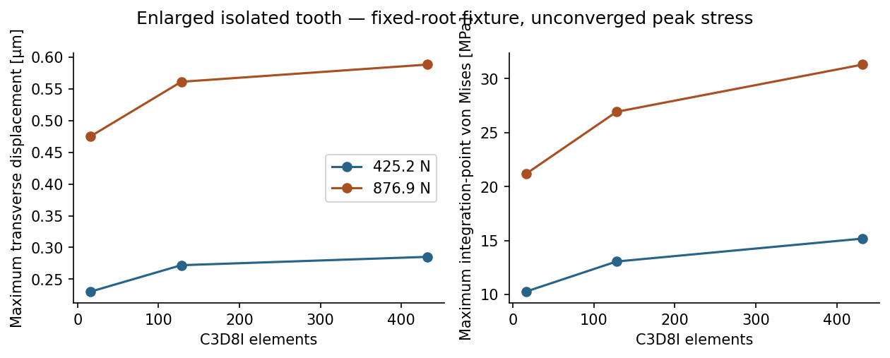
Local source,23 native/STEP pairs including the separate contact coupon, reports and retained failures. False lock indication, a gate falling onto a straddling payload and missing actual sled custody remain physical counterexamples. No feeder is selected.
Limited orbital replenishment
The RPL-01 concept defines cooperative-cartridge datums, capture/retention, isolation, contamination, operations and faults. 108 capture sensitivities and 36 insertion cases retain 18 failed fits. Current integration does not support an operational reload claim; ground loading remains the campaign assumption.
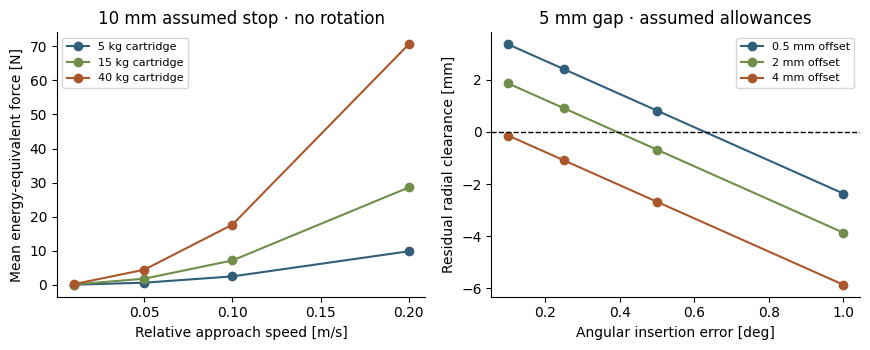
Feasibility report, provisional interface and source calculations.