The passive cage
A 318.6 mm, five-lane magnetic/copper interface. No payload power or command electronics. Attachment, remanence, tolerance and compatibility remain engineering obligations.
A passive magnetic and copper interface on the payload. Powered windings on the launcher. A design study asking whether that trade can remove the moving sled, its brake and its return stroke.
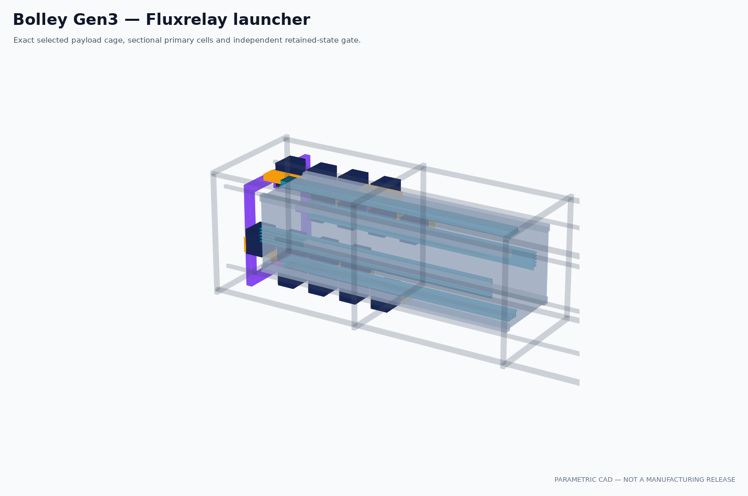
VOLLEY aims to leave the payload unmodified. BOLLEY tests the neighbouring premise: accept a passive spacecraft interface and count what the launcher can remove.
A 318.6 mm, five-lane magnetic/copper interface. No payload power or command electronics. Attachment, remanence, tolerance and compatibility remain engineering obligations.
Four face channels, 27 cells per face, 45.3 mm pitch. The 1.2231 m primary contains 15.908 kg of modelled material before structure, cooling, wiring or electronics.
The selected power modules alone add 2.5488 kg. Removing a sled does not establish a lighter complete system. A packaged allocation and payload-side mass accounting are still required.
A passing calculation can support rejecting a machine. The repository preserves the failed geometry and the requirement that changed.
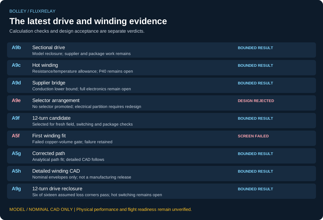
A10 exposed the contradiction. The reference target became 11.8 m/s; the earlier requirement and failed result remain recorded.
A9f selected twelve turns at fixed 1,520 A-turn MMF. That preserves an ideal field screen, while resistance and inductance rise and the actual conductors still need field reclosure.
A5f missed copper volume. A5g corrected the path; A5h passed ten nominal conductor-envelope bands. Manufacturing and terminal geometry remain open.
The selected handoff envelope reproduces turn scaling. Just six of sixteen assumed conduction/additional-loss corners stay below the reference-shot energy cap.
Start at the selected A9f reference point: 870.815987 J of non-inverter machine energy plus 18.903094 J of bridge conduction under its 25 °C assumption.
Change the assumed conduction resistance and add other losses. The 900 J cap stays fixed. This is the A9g accounting sensitivity, not a temperature curve or a switching simulation.
Inspect all sixteen cases ↗WITHIN THE ASSUMED ENERGY CAP
No credit for an unselected cooling system, switching strategy or recovered energy.
Actual winding/lead field, RMS and peak current definitions, hot conduction, switching, protection, bus sag and thermal recovery in one configuration.
Lane tolerance, cage attachment, independent retention, failed-channel loads, six-degree-of-freedom departure and tip-off.
One complete installed budget, drawings, BOM, instrumentation, assembly/inspection process and frozen acceptance criteria.